PistormX 500 DIP / Build Log, From SRAM Hunt to Burned Chips and Back (part 2)
Building my own PistormX 500 DIP for the Amiga 500: finding an affordable SRAM, learning Xilinx ISE the hard way on Windows 11, and a long story about four dead CPLDs, a wrong regulator, a 2.8 ohm short, and how the Raspberry Pi I was using to flash kept killing the chips. Still not fully working, but a lot closer.
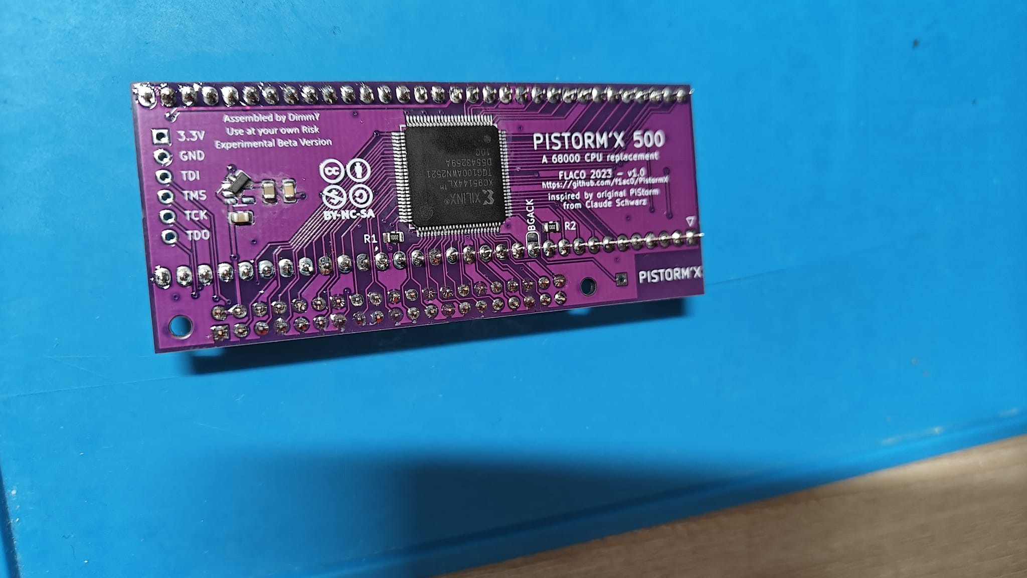
The PistormX 500 DIP is FLACO's variant of the original PiStorm by Claude Schwarz, designed for an Amiga 500 with a DIP-socketed 68000. The board uses a Raspberry Pi as the emulated CPU and a Xilinx XC95144XL CPLD as bus glue, with an optional 2 MB SRAM on the back as Fast RAM. On paper it's clean and simple. In practice this build took me through every kind of failure I can think of. Here's the full story. (part one is here)
1. Read part one for more on the first software build.
Part one of this project
There is a lot of overlap in this part, but if you want more details read part 1 first
2. Flashing the CPLD: pick your method
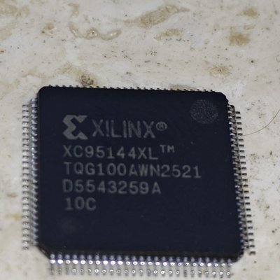
The board has a Xilinx XC95144XL TQ100 CPLD. It needs to be programmed via JTAG. I had two options:
- Use the on-board PROG header (J3), which exposes TDI, TMS, TCK, TDO, GND and 3V3 on six pins. Wire a Pi GPIO to each pin with dupont cables.
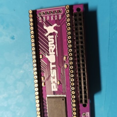
- Plug a Pi straight onto the J2 socket. The schematic routes the same four JTAG signals through the Pi GPIO header, so the Pi can flash the CPLD it later runs on.
Option 2 looked easiest — just plug the Pi on and run a command. So that's what I started with. This turned out to be the worst possible choice. More on that in a minute.
The JTAG-to-Pi-GPIO mapping I traced from the KiCAD schematic:
JTAG signalPi GPIOPi header pin TDIGPIO2713 TMSGPIO2418 TDOGPIO2522 TCKGPIO26373. Xilinx ISE 14.7 on Windows 11 — choose your suffering
To build the CPLD bitstream I needed Xilinx ISE 14.7. It's from 2013, was last supported on Windows 7, and depends on a VC++ 2008 SP1 runtime that Windows 11 doesn't really want to play nice with.
I tried three things:
- The "ISE 14.7 for Windows 10" VM installer failed because of a Hyper-V conflict (Docker uses it).
- The native installer hung at 90% on a WebTalk DNS call. After killing it, the install was actually mostly complete, but the VC++ runtime detection was broken. xst -help just hung forever. Reinstalling the redistributables from Microsoft did nothing.
- VirtualBox 7 with the official ISE Linux VM, using Windows Hypervisor Platform to coexist with Docker. This just works. Docker keeps running, the Linux VM boots, ISE opens.
Lesson: if you're on Win11 with Docker installed, go straight to option 3. Don't even try the native installer. I lost a few hours figuring this out.
4. First build, first flash attempt
Inside the VM the ISE flow is straightforward: new project targeting XC95144XL-10-TQ100, add the three source files (pistormx500.v, ram_autoconfig.v, pistormx500.ucf), Synthesize, Implement, Generate Programming File. iMPACT exports an SVF or XSVF. A shared folder in VirtualBox drops the output straight into my Windows working directory.
For the very first flash, while I was still waiting for the SRAM to arrive, I flipped a define in the Verilog from RAM_AUTOCONFIG to RAM_NONE so the CPLD wouldn't try to talk to an SRAM that wasn't there. Re-built, exported a fresh SVF.
I copied the SVF to a Pi 4, installed openocd, made a small config telling it to bitbang the four GPIO pins as JTAG. Plugged the Pi onto J2. Powered up.
5. CPLD #1: cooked
Within a few seconds I could not touch the CPLD without burning my finger. I'd never had a chip get that hot. I yanked the power. The chip was effectively dead — it could only barely respond to JTAG, the bitstream wouldn't program.
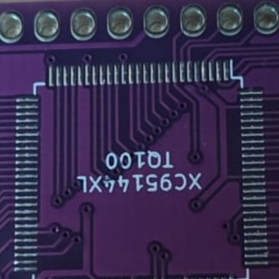
My first guess was that I'd soldered the CPLD the wrong way around — TQFP-100 markings are subtle and the silkscreen on this board is oriented opposite to the rest of the labels. Spent an evening peering at chip corners under a loupe.
Ordered a new XC95144XL.
6. CPLDs #2, #3, #4: also cooked
With a fresh chip in, same story. Hot within seconds. After the third one died I stopped and forced myself to actually understand what was going on, instead of just replacing chips and hoping.
Two things were happening at the same time:
- The 3V3 regulator wasn't a 3V3 regulator. The board has two alternate footprints for the 3V3 LDO: a SOT-23-5 (SPX3819) and a SOT-23-3 (XC6206). Most builds use the cheaper XC6206. I had installed something in the SOT-23-3 spot, marked "BAT54C". Which is not a regulator at all. It's a dual Schottky diode. The pinout sort of looks similar, but one of the internal diodes was forward-biased between 5V and GND, the other was between Vout and GND. The 3V3 rail was floating somewhere around 2.4 V with peaks much higher. Every CPLD I dropped on the board was being fed garbage power.
- Plugging the Pi onto J2 powers the CPLD through its I/O pins. The Pi's GPIO sit at 3.3 V the moment the Pi has USB-C power. The board's CPLD VCC ramps up later, through the regulator. During that gap the Pi is driving signals into a CPLD that isn't fully powered yet. The internal ESD diodes then start conducting current from the I/O into VCC, and the chip can latch up. This is a well-known failure mode, I just didn't know it existed.
So I'd been picking the worst combination: a wrong regulator giving the CPLD an unstable supply, plus a flashing method that injected current backwards into the chip during boot. Each CPLD got a few of those cycles before quietly dying.
7. Fixing the power section
Pulled the BAT54C off, ordered a proper XC6206P332MR (LCSC C5446, about €0.05 each — I got five). Soldered it back on in the right orientation (the XC6206 has Vout on pin 2, not pin 3 — easy to get wrong).
Powered up. New chip CPLD #5 stays cool, like it should. Measured the 3V3 rail at J3 pin 6.
2.4 V. Still 2.4 V. Different chip, same number.
Put the multimeter on resistance, board off: 2.8 Ω between 3V3 and GND. A near-perfect short somewhere on the rail. The XC6206 was current-limiting, dumping everything into the short, and outputting whatever voltage that left over.
8. Chasing the short
I pulled the SRAM off first — that was my prime suspect because it's on the same rail and could've been damaged when the rail was overvoltage with the BAT54C in place. Still 2.8 Ω. Pulled the regulator. Still 2.8 Ω. Checked every passive around it.
Eventually I traced it to the CPLD itself. The chip I'd just soldered on tested as a short. Brand new from the bag and dead before it ever saw clean power.
Looking back, I think the problem is the cycle:
- I install a fresh chip.
- I plug the Pi onto J2 to flash. The I/O pins push current into VCC before the regulator stabilises.
- The chip latches up. It might still respond to JTAG IDCODE, but it now has an internal VCC-to-GND short.
- Resistance test confirms the short, I think "must be a different component", waste time hunting.
Four CPLDs in. Costly mistake to learn.
9. The actual safe way to flash
From that point I stopped using the Pi-on-J2 method entirely. Instead:
- Pi sits on the bench, not on the board.
- Six dupont wires from the Pi GPIO to the J3 PROG header: TDI, TMS, TCK, TDO, GND, plus 3V3 from the Pi's own onboard regulator to feed the PistormX directly. This bypasses the board's regulator entirely during programming.
- Pi USB-C only goes in after all the wires are attached, so the CPLD power and JTAG signals come up roughly together.
With this setup the CPLD stays cool, the 3V3 rail is solid, and the chip survives the flash. Highly recommended over the "Pi on top" route.
10. The SVF clock trap
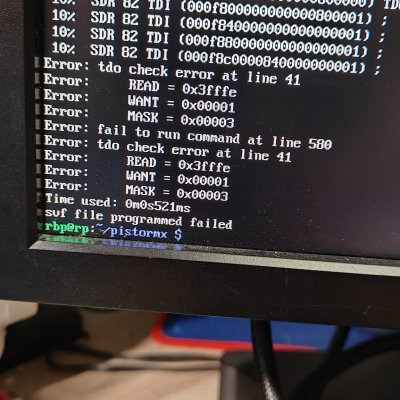
Even with all hardware right, the first openocd flash bombed at 10% with TDO verify errors. I dropped the clock to 100 kHz in pistormx.cfg and got the same error.
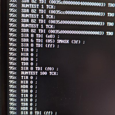
Turns out the SVF file itself contains a FREQUENCY 1E6 HZ; command. When openocd hits it during processing, it overrides my config and ramps the clock back up to ~1 MHz. Dupont wires don't handle 1 MHz JTAG well, signals get reflected, verify fails.
Fix: opened the SVF in nano on the Pi, changed that line to FREQUENCY 1E4 HZ; (10 kHz). Ran openocd again. It chugged through for about five minutes and finished without a single error. CPLD programmed.
11. Where I am now
Where I am right now, while writing this: the CPLD is programmed, the regulator is correct, the 3V3 rail is stable, the SRAM is back on the board, the mandatory CLK-to-OVR patch wire from the README is in. I bring the board over to my Amiga 500 Rev 6 — the same Amiga that runs an original PiStorm without any issue, same Pi, same SD card. Swap PiStorm for PistormX.
The Pi keeps rebooting. I see the Emu68 logo flash for a second, then it's gone, then it comes back. Loop.
I haven't cracked this one yet. Suspects in order:
- Subtle soldering issue on one of the bus signals from the CPLD to the J1 socket (100 pins, only takes one bad joint).
- The SVF I rebuilt myself might be subtly different from FLACO's pre-built one, even though functionally it should be identical.
- One of the four "previously dead" CPLDs left a damaged trace or via under solder mask that I can't see.
The FLACO repo is clear that this board is experimental and not all builds work. The official place to get help is the "beta-testing-pistormx" channel on the PiStorm Discord, where other people who have built one can compare notes. That's my next step.
12. Things I'd tell my past self
- Read the README in the Beta directory twice before you start. The CLK-to-OVR patch wire and the BGACK jumper note are easy to miss.
- Don't trust the BOM blind. Verify each part by its markings before you solder. "BAT54C" is not a regulator no matter how much it sounds like one.
- For Xilinx ISE on Windows 11 with Docker installed, just go straight to the VirtualBox + Linux VM route. The native installer is a dead end.
- Never plug a Pi onto an unprogrammed CPLD that's still being powered up. Use the PROG header with the Pi physically separated from the board, and let the CPLD's VCC come up cleanly before any GPIO touches it.
- When ordering anything that might break: order two of it. The €5 difference is nothing compared to the time you save not waiting for a second shipment.
Status: CPLD programmed, hardware in place, still chasing the boot loop on the Amiga. To be continued.
References
- PiStormX: https://github.com/f1ac0/PistormX
- Original PiStorm: github.com/captain-amygdala/pistorm
- Xilinx ISE 14.7 download archive: AMD/Xilinx support downloads
- xc3sprog: xc3sprog.sourceforge.net
- IS61WV102416BLL datasheet: ISSI (LCSC part C28124)