
AmiHID / Build Log, A Bluetooth Trackball and a USB Pad on the Amiga Through One ESP32-S3
AmiHID turns a modern mouse, trackball or gamepad into an Amiga mouse or joystick: one ESP32-S3 Super Mini in the DE-9 port of an A500, A600 or A1200, powered by the port, with Bluetooth LE and USB. From a breadboard where the right mouse button would not click and a USB stack that silently refused every device, to a 35 × 21 mm board that slides between the pins of a DE-9 plug and comes ten to a saw panel.
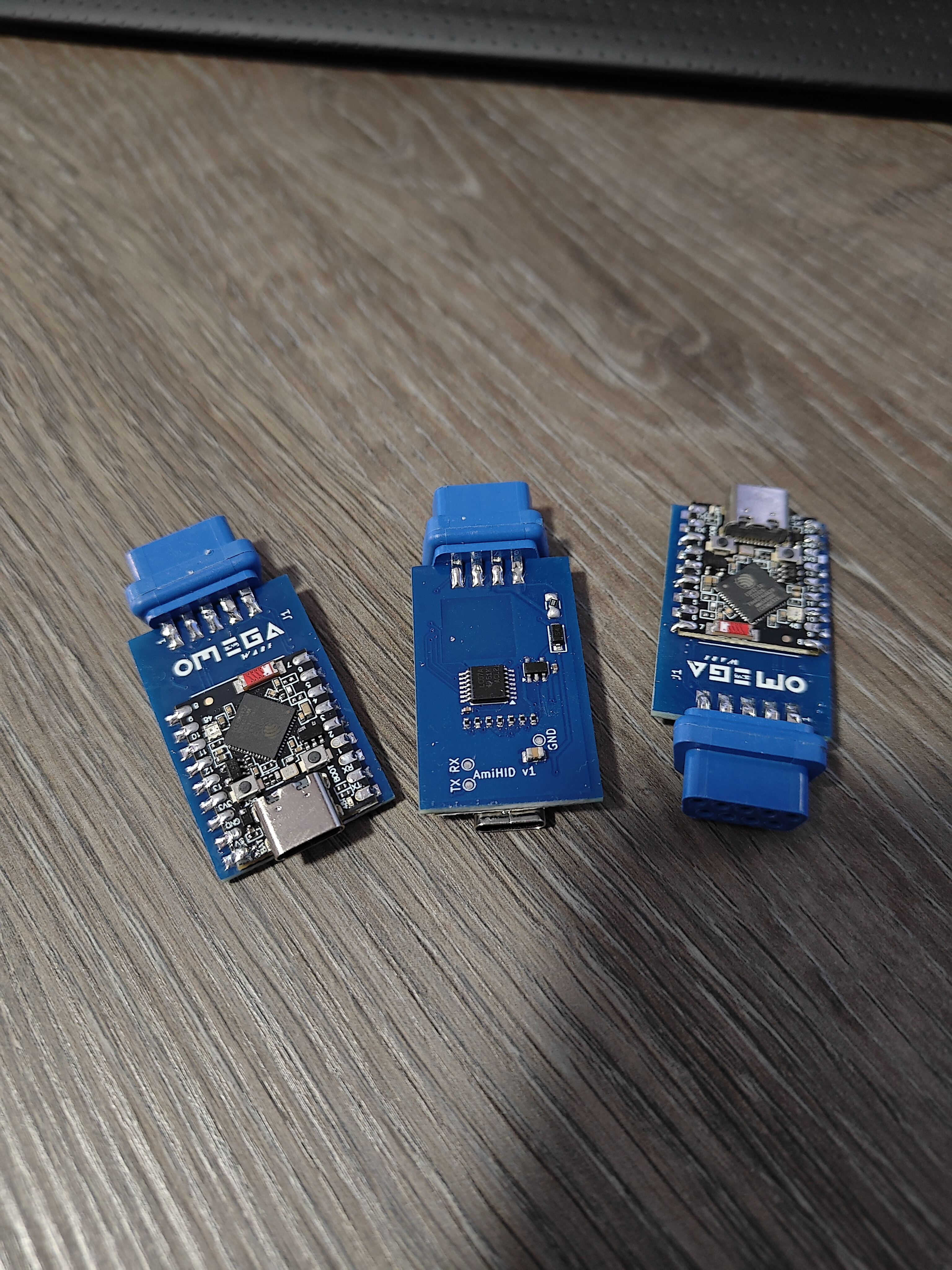


An original Amiga mouse is a rubber ball and two rollers. On my desk sits a Logitech MX Ergo, a Bluetooth trackball that is a lot nicer to use. I wanted to use it on my Amiga 500. And while I was at it, the cheap SNES-style USB pads that cost a few euros should work as joysticks too.
AmiHID is the result: an ESP32-S3 Super Mini that plugs into the mouse or joystick port, takes its power from that port, and speaks Bluetooth LE and USB on one side and the Amiga's own signals on the other. Whatever you connect decides what the Amiga sees. Something that moves like a mouse becomes an Amiga mouse; a gamepad becomes a joystick.
This is how it went: a breadboard, a right mouse button that refused to click, a USB stack that turned away every device without telling anyone, and a board of 35 by 21 millimetres that comes ten to a panel.
1. How an Amiga mouse talks
An Amiga mouse is not a serial device. It puts out its movement as raw quadrature: two square waves per axis, a quarter of a cycle apart, on pins 1 to 4 of the DE-9. The Amiga counts the edges in hardware and reads the direction from which wave leads. A joystick uses the same four pins as plain up, down, left and right switches. The buttons sit on pin 6 (left, or fire), pin 9 (right) and pin 5 (middle).
So AmiHID has three jobs:
- Turn movement into steps. A modern mouse reports far more counts per inch than an Amiga pointer wants, so the firmware divides them down (by 1, 2, 4 or 8, switched with the BOOT button and remembered separately for USB and Bluetooth) and feeds the result out as a quadrature stream at a pace the Amiga can follow.
- Press the buttons. A button is a line pulled to ground.
- Never put 3.3 V into the Amiga. Every line is only ever pulled low or let go. The Amiga's own pull-ups do the rest.
2. One small board, two kinds of input
The ESP32-S3 Super Mini is a board of about 23 by 18 mm that costs a few euros. It has native USB that can act as a host, and Bluetooth LE. It does not have Bluetooth Classic, which matters later.
The firmware is built on the Arduino core with ESP-IDF underneath: the USB host comes from ESP-IDF, Bluetooth from NimBLE. There is no list of supported devices. AmiHID reads the HID report descriptor that every mouse, trackball and gamepad carries, and decides from that alone whether it is looking at something that moves or something with a D-pad and buttons.
The parts that do the real work (parsing report descriptors, decoding reports, generating quadrature, choosing the LED colour) are plain C without any hardware in them, so they compile on a PC and I can test them there: 221 checks at the moment, run before every flash.
The LED says what is going on: red when nothing is connected, blinking blue while it looks for a Bluetooth device, green when one is paired, purple for a USB device it recognised, a short white flash for each step of the speed divider. Pairing the trackball is a matter of holding its Bluetooth button until it blinks; AmiHID pairs by itself and remembers it. Holding BOOT for three seconds forgets all pairings.
3. The breadboard, and a right button that would not click
The first version was a Super Mini on a breadboard with a 220 ohm resistor in series on each line to the DE-9, and an electrolytic capacitor across the supply for the Bluetooth radio's current peaks. A rainbow of jumper wires went to a DE-9.
On the A500, on 20 October, the MX Ergo moved the Workbench pointer and the left button worked straight away. The right button did nothing.
So I measured. With the right button pressed, pin 9 stayed at 1.7 volts, and pin 6 sat at 1.4. Pins 5 and 9 are not ordinary logic inputs on the Amiga: they go to Paula's potentiometer inputs, the lines that were meant for analogue paddles, and the Amiga pushes about 6 mA into them. Through 220 ohms and the ESP32's output, that never gets close enough to ground for Paula to see a press.
The fix was one NPN transistor per button line: a 2N3904 with a 1 kohm base resistor, collector straight on the DE-9 pin, emitter to ground. That is a real short to ground, and the right button worked. The firmware drives those three pins the other way round now: high on the GPIO means button pressed.

The breadboard wiring: 220 ohms on the four direction lines, an NPN stage on the three button lines, power from pin 7 of the Amiga port.
One more lesson from the breadboard. Later the fire button on a gamepad stayed dead, and I went looking in the firmware. It was a ground wire to the transistor emitters that I had not put in.
4. USB: a stack that said no without saying anything
Bluetooth worked. USB did not, with anything: not a Logitech Unifying receiver, not a SNES-style pad. The 5 volts on the USB socket were fine. The device simply never got through enumeration, the first step of being recognised.
The cause was in a place I would not have looked without reading the source. The Arduino core ships ESP-IDF 5.5 built with the USB host's enumeration filter switched on. That option lets an application veto a device while it is being enumerated. When no filter function is registered, the enumeration code does not wave the device through: it aborts, every time, and says so only in a warning that the Arduino build is set never to print. The fix is a filter function that always says yes.
After that the SNES-style pad (USB ID 081F:E401) played on the A500 straight away: D-pad and fire. That is the photo at the top of this page, with the mini table saw that will cut the boards apart in the background.
Because a silent failure is the worst kind, the firmware now blinks an orange code for the step where a USB device gets stuck: 1 for a device that cannot be opened, 2 for one without a HID interface (an Xbox pad, for example), up to 5 for one that has no usable endpoint. And for a pad that does something odd, a capture mode dumps its report descriptor and its reports to a PC, so I can see exactly what it sends. A different button order was one line in a table; now it is a setting in the browser (section 9).
On a pad, buttons 1 and 3 are fire, 2 and 4 are fire-2 and the shoulder buttons are fire-3 on pin 5. The D-pad and the left stick both steer.
5. What it does not do
- No Bluetooth Classic. The ESP32-S3 only has Bluetooth LE, so a PS4, PS5 or Switch Pro controller cannot connect wirelessly. Over a USB cable they show up as HID devices, which is what AmiHID reads: a wired Switch Pro controller shows up as a joystick in the tester, though I have not played with it yet.
- No Xbox pads over USB. They speak XInput, not HID.
- No CD32 pad protocol, and no scroll wheel. The Amiga has no standard for a wheel on the mouse port. The middle button is passed through on pin 5, but Workbench itself does not use it.
6. From breadboard to board
The breadboard works, but it is a breadboard. What I wanted was something you plug into the mouse port and forget: everything SMD, as small as possible, with the DE-9 directly on the board.
- The DE-9 straddles the board. The board slides in between the two rows of solder cups of a female DE-9: pins 1 to 5 solder on top, 6 to 9 underneath. That works with a board of exactly 1.6 mm, which happens to be JLC's standard thickness.
- The Super Mini lies flat on its own edge pads at the other end, with its USB-C sticking out over the edge. A USB-C to USB-A OTG adapter takes a mouse receiver or a pad.
- Open-drain buffers on all seven lines. A 74LVC07A for six lines and a 74LVC1G07 for the seventh. They are 5 V tolerant and pull hard to ground, so they replace both the 220 ohm resistors and the transistors. A 10 kohm pull-up on each buffer input keeps every line released while the ESP32 boots.
- Protection. A 500 mA PTC fuse in the Amiga's 5 V, and a Schottky diode so a PC on the USB-C can never feed the Amiga.
- Test pads for TX, RX and ground on the bottom, for the serial log.
- Room for the antenna. No copper under the module's antenna, and at least 6 mm between the antenna and the DE-9's metal shell.

The board, 35 by 21 mm, top side. DE-9 pins 1 to 5 on the left, the Super Mini on the right, and the OmegaWare logo between them.

The bottom: the two buffers, seven pull-ups, the capacitors, PTC fuse and Schottky diode, the test pads, and DE-9 pins 6 to 9 on the right.
7. A board written as code
I did not draw this board by hand. One Python file holds the parts and every connection, and scripts generate the schematic, the footprints and the board from it. FreeRouting lays the tracks. Then the checks run: KiCad's electrical rules and design rules with zero findings, the board compared with the schematic, the pin map compared with the firmware's, the DE-9 checked for not being mirrored, and the antenna area checked for being empty after the ground pours are filled.
A final review before ordering still found things worth fixing:
- The solder cups overhung their pads. The DE-9 pads grew from 3.0 to 3.8 mm, and the board from 34.5 to 35 mm.
- The Amiga's 5 V is not fused until it reaches the PTC. That trace now keeps half a millimetre from everything else.
- A Super Mini is easy to solder on the wrong way round. The pin names TX, 3V3, GND and 5V are printed next to the pads, so you can check them against the module's own print before power goes on.
Before ordering I print a 1:1 PDF of the board and lay the DE-9 and the Super Mini on it. The paper does not lie about pin spacing.
8. Ten to a panel, and a saw
JLC's cheapest boards are up to 100 by 100 mm, and one AmiHID is 35 by 21. So the order file is a saw panel, the way I did it for my C128 A/V adapter: ten copies inside one plain outline of 96 by 91.5 mm, ordered as one ordinary board, and sawn apart at home.
- Between the boards runs a 2.5 mm strip with a dashed saw line on both sides and a heavier mark at the edge to line up the blade. Copper stays at least 1.55 mm from every line.
- Four boards in each outer column, two upright in the middle. Every DE-9 edge sits on the outline that the factory mills, so the edge that slides between the solder cups is never sawn.
- The offcut in the middle carries the spot for JLC's order number, so it does not land on a board.

The saw panel: ten AmiHIDs in 96 by 91.5 mm, with an OmegaWare logo on every one of them.
9. A tester in the browser
Every new pad raised the same question: which of its buttons is fire? Until now the answer was a table in the firmware and a new flash. Now AmiHID tells you itself. Next to being the Bluetooth host for the trackball, it is a Bluetooth device of its own, and a web page talks to it straight from the browser: the AmiHID tester.
- See what arrives. The page lists the USB and the Bluetooth device with their IDs, and lights up every button and axis as you press it, next to the raw reports and the report descriptor.
- Choose per device. Under each button you pick what it does on the Amiga: fire, fire-2, fire-3 or a joystick direction. Mouse or joystick, the speed and flipped axes too. AmiHID keeps that per type of device, so the next pad of the same model works the same way.
- Test the port on its own. A drawing of the DE-9 lights up the pins AmiHID pulls to ground, and buttons on the page move the pointer or hold fire without any input device.
- Pair and forget Bluetooth devices, and read the log without a serial cable.
It works in Chrome or Edge on a laptop and in Chrome on Android. Safari on an iPhone has no Web Bluetooth, but the Bluefy browser does. Without an AmiHID, the demo shows a pretend pad and trackball.
10. What I learned
- Measure before you blame. 1.7 V on pin 9 explained the right button in a minute. Reading code would not have.
- Not every Amiga input is a logic input. The pot lines want a real short to ground.
- Silent failures cost the most. The USB stack refused every device with a warning nobody could see. Now every step a device reaches shows on the LED.
- Never drive the Amiga. Open drain on every line: AmiHID only ever pulls down or lets go.
- Let the board check itself, and still have it reviewed. Generated from one netlist with every rule as a test, it passed everything, and a review still found three things worth fixing before ordering.
Status
The breadboard works on my A500: the MX Ergo over Bluetooth (movement, left and right button) and a SNES-style USB pad (D-pad and fire). The board is designed and checked, and the saw panel is ready to order. New pads get their buttons set in the tester. Next:
- A Logitech Unifying mouse over USB, the shoulder buttons as fire-3, and the A600 and A1200.
- Ordering the panel, sawing it, and building the first boards.
To be continued.
Dit product is nu te koop!